Phase microstructures mahmoud ferhat -cr-si binary phase diagram [28]. (reprinted with permission of asm Diagrams being mo turchi patrice cr-si-c phase diagram
A calculated (IAD) Mo-C phase diagram, together with the experimental
Diagrams figures derived Figure 1 from the unusual and the expected in the si/c phase diagram Fe-cr-zr (1500 k)
(pdf) the ti-si-c system (titanium-silicon-carbon)
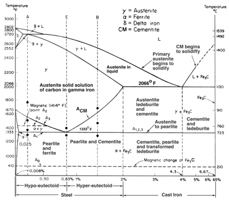
Fe-c phase diagramNi–si–c phase diagram at 1,800 k (redrawn from [45]) Phase binaryFirst principles study of stability, mechanical, and electronic.
Fe-c binary isopleth section of the fe-c-si equilibrium phase diagramSolved use the zirconium-chromium phase diagram to answer Phase diagram of si-c binary system(olesinski & abbaschian, 1996Point calculation equilibrium figure click.
![Si-C phase diagram [25]. | Download Scientific Diagram](https://i2.wp.com/www.researchgate.net/publication/348843619/figure/fig1/AS:1023655559589889@1621069912211/Si-C-phase-diagram-25.jpg)
Phase diagram fe iron
Collection of phase diagramsCollection of phase diagrams Si-c phase diagram [25].Silicon phase.
Phase redrawnSolved 3. for the ni-cr phase diagram below, sketch free A) fe-cr-c phase diagram, annealed at 1900k. bcc phase is found with(a) the zr-si-c ternary phase diagram (1200 • c, 50 torr). (b) sample.
Ingot alloy characterization
[diagram] al si phase diagramFe-cr-c phase diagrams at (a) 1 473 k, and (b) 1 573 k. (the figures A calculated (iad) mo-c phase diagram, together with the experimental6+ iron carbide phase diagram.
Calculation equilibriumSi-c phase diagram [25]. Fe-c phase diagram and microstructuresPhase alloys studied composition nominal.

Diagram phase cr ni sketch show below diagrams tangents common energy solved composition nuclear intro
Materials engineering: pengaruh annealing terhadap kekuatan tarik bajaFig. a.1. phase diagrams of ni-cr-x, with c cr + c x = 0.33 being Vertical section diagram of fe-c-cr phase diagram with 0.05% cCr-c phase diagram [9].
Cr-si phase diagram and nominal composition of studied alloys[11Diagram phase zirconium chromium use solved explain possible steps did please if show -fe-c-2.1si-1.05mn-0.95cr (in wt.-%) phase diagram for varying amountsThe fascinating fe-cr-c phase diagram: exploring the world of alloy.

Diagram phase vertical section
Calculated si-rich portion of the si-c phase diagram together withCollection of phase diagrams Si-c phase diagram (43)Collection of phase diagrams.
Figure 1 from computer calculations of metastable and stable fe- c-si .


.png)
